How to Use This Tool
- Enter each primary channel from 1 to 13 and its 20 or 40 MHz width.
- For each 40 MHz entry, confirm the secondary channel is above or below the primary. An unknown direction cannot produce a result.
- Read the primary and bonded centres, nominal edges and overlap. Check the router’s actual configuration and local channel availability separately.
Calculation Method
Primary centre = 2407 + 5 × channel MHz. A 20 MHz span extends 10 MHz either side. At 40 MHz, the secondary is four channel numbers above or below, and both must remain within 1–13. The bonded centre moves 10 MHz towards it; nominal edges extend 20 MHz either side. Overlap is the shared interval width.
Worked Example
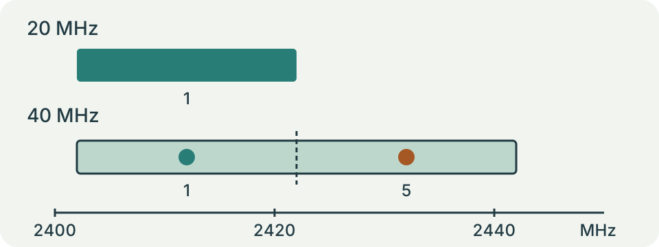
Channels 1 and 4 at 20 MHz have centres 2412 and 2427 MHz: 15 MHz apart, with 5 MHz nominal overlap. Primary 1 with a secondary above uses channel 5, bonded centre 2422 MHz and nominal edges 2402–2442 MHz.
Read Settings Rather Than Guessing Them
Copy the primary channel and current width from the router's radio status or a suitable local Wi-Fi analyzer. A setting labelled automatic may not identify the channel currently in use. Record the band too: this checker covers 2.4 GHz channels 1 through 13, not similarly numbered channels in other bands. The page cannot scan neighbouring access points or inspect your router through a browser.
For each 40 MHz entry, obtain the secondary channel direction. Above and below locate different bonded spans even with the same primary channel. A display that only says channel 6 and 40 MHz leaves required information missing. Consult the equipment's documentation or status information instead of selecting a direction at random.
Channel Numbers Are Not Megahertz of Separation
For the supported primary channels, the centre frequency is 2407 plus five times the channel number, in MHz. Channel 1 is centred at 2412 MHz and channel 2 at 2417 MHz. Their centres differ by only 5 MHz even though each nominal 20 MHz span is much wider. Adjacent channel numbers do not represent isolated slices of spectrum.
The diagram draws each nominal span as a rectangle. For a 20 MHz entry, its edges lie 10 MHz either side of the centre. Channel 1 therefore spans 2402–2422 MHz in this model. Those edges describe the calculation, not a sharp boundary beyond which a real transmitter emits nothing.
Locate a Bonded 40 MHz Span
A secondary channel above is four channel numbers above the primary; below is four below. Primary 1 with secondary above therefore uses channel 5. The bonded centre lies halfway between the two constituent centres, at 2422 MHz. Its nominal 40 MHz span is 2402–2442 MHz. Centring that span on primary channel 1 would place it incorrectly.
The tool requires both constituent channel numbers to remain within its supported 1–13 range. Primary 13 with secondary above is rejected, as is primary 1 with secondary below. An unknown direction also produces an error. These boundaries are model checks, not a declaration that every other combination is available on a particular device or permitted locally.
Check the Overlap Arithmetic
At 20 MHz, channel 6 has a centre of 2437 MHz and nominal edges of 2427–2447 MHz. Compared with channel 1 at 20 MHz, their rectangles do not overlap. Compared with primary 1 at 40 MHz above, the shared interval is 2427–2442 MHz, giving 15 MHz of overlap. Width and secondary direction can therefore change the result without changing the primary number.
Overlap is the smaller upper edge minus the larger lower edge, with negative results replaced by zero. Two channel 1 entries at 20 MHz have 20 MHz overlap. Two intervals that only touch at an edge have zero shared width. Centre spacing is a different output and should not be read as the overlap value.
| A: primary / width / secondary | B: primary / width | Centre spacing (MHz) | Overlap (MHz) |
|---|---|---|---|
| 1 / 20 MHz | 2 / 20 MHz | 5 | 15 |
| 1 / 20 MHz | 6 / 20 MHz | 25 | 0 |
| 1 / 40 MHz / above | 6 / 20 MHz | 15 | 15 |
Separate Overlap from Interference
A positive result shows shared nominal frequency space. It does not measure traffic, received power, retransmissions or how long a channel is occupied. Two access points far apart may share a channel without causing the same local problem as nearby busy equipment. Networks on the same channel also differ from overlapping-channel arrangements, so the largest overlap value alone cannot select the worst configuration.
A zero result is not a guarantee of clean reception. Real spectral shapes, receiver behaviour and other sources remain outside these rectangles. The checker does not model Bluetooth activity, appliances or hidden transmitters. Investigate a repeatable connection problem with actual observations rather than treating the diagram as a recorded radio scan.
Make a Controlled Change
Write down the existing configuration before changing a setting through the router's supported interface. Confirm local channel availability and client support separately. Keep one device in the same place and repeat the same task before and after a single change. Moving the device, changing width and switching bands together makes the cause of a difference unclear.
Use the application's actual transfer rate or interruption record to judge the original problem. A short speed peak may not explain a call that disconnects later. A path-loss estimate can illustrate distance in an ideal model but cannot supply the missing measurement of the building. Avoid turning geometric calculations into a recommendation to raise transmit power.
Know When This Checker Cannot Answer
Channel 14, 5 GHz and 6 GHz need different mappings and are deliberately outside this form. Channel numbers alone are ambiguous without a band. A rejected input should lead back to the recorded settings, not to rewriting the number until the page accepts it. Reset restores the example of channels 1 and 6 at 20 MHz; it changes no router setting.
The diagram updates from entered parameters and remains a teaching graphic. Keep the original settings, measurement time and observed symptom together when asking for help. That record is more useful than a claim that a particular overlap percentage proves the best channel.
What the Result Means
Rectangular spans simplify spectrum geometry. Real emissions, spectral masks, traffic, signal strength and receiver behaviour affect interference. Channel 14, 5 GHz and 6 GHz are outside this checker. A valid combination here is not regulatory approval.
Common Questions
Does Zero Nominal Overlap Mean No Interference?
No. Real emissions and other sources can affect reception beyond these simplified edges.
Can a Primary Channel Alone Locate a 40 MHz Span?
No. The secondary direction is required; the full span is not centred on the primary.